Posted: January 1, 2013
Clutch Modeling - Part I: Friction Clutches
Note: Javascript is required on this page to properly typeset equations.
Introduction
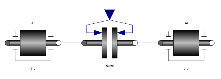
One area that Modelica excels at is the modeling of clutches. For our purposes, we will examine a simple system where two rotational inertias are coupled through a clutch as shown in Figure 1.

Just as a bit of background for those unfamiliar with clutches, they have essentially two modes of operation. In the "open" or "disengaged" mode, they allow the two elements on either end to move freely with respect to each other. But when the clutch switches to the "closed" or "engaged" mode, it couples the motion of the two elements together so that they are forced to spin at the same speed. The main application for clutches is in automotive transmissions although there are certainly other applications. The web site HowStuffWorks has even more information on how clutches work
For this discussion, we will study two different types of clutch models. As is always the case in modeling, the choice of model (which includes decisions about behavior, level of detail, etc) depends on the application for the model. In each of the following sections, we will discuss one particular type of clutch model and under what circumstances each model is typically applied.
Friction Clutch
The "normal" clutch model (e.g. the one found in the Modelica Standard Library) is a frictional clutch model. Friction clutch models are interesting because they have two different distinct kinds of behavior. We will call these the "slipping" behavior and the "sticking" behavior.
Slipping
The slipping behavior occurs when the two sides of the clutch are rotating at different speeds. As the clutch "plates" come into contact with each other, they rub against each other. The amount of friction generated by this rubbing is proportional to the normal force, Fn applied to the plates (i.e. how hard the plates pushed together). For a given friction coefficient, μ, we can compute the frictional torque between the plates with the following equations:
τ=cgeoμFn
Some readers may be more familiar with calculation of the friction force as:
Ffric=μFn
However, with rotating plates, there are frictional forces distributed
across the plate. We use the "geometry factor", cgeo, to
represented the cumulative effect of all the local friction forces
multiplied by the distance of that force from the center of the
plate's rotation in order to compute the cumulative torque applied to
the plate. A more rigorous discussion of the geometry coefficient can
be found in the Clutch model documentation from the Modelica
Standard
Library.
One last detail about modeling of slipping is that the friction coefficient, μ, is a function of the relative speed between the clutches. So a more complete equation for the frictional torque would be:
τ=cgeoμ(Δω)Fn
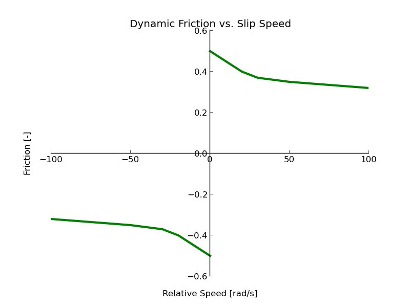
In the Modelica Standard Library, the frictional clutch model includes a table used to compute the friction coefficient as a function of (absolute) relative speed across the clutch. Figure 2 shows an example of how the friction coefficient, μ, might be a function of relative speed, Δω.

Sticking
So far, we've only been talking about the slipping behavior. Now we turn our attention to the "sticking" mode. In the sticking mode, the behavior of the clutch is easy to represent mathematically. It can be captured by this deceptively simply equation:
Δω=0
This equation essentially says that when the clutch is "stuck", we compute the torque such that the speed difference remains zero. But this is where the trouble starts. If you think about a spring, a damper or even a slipping clutch, they all fit in the general form:
τ=f(Δθ,Δω)
In all these cases, we always have a way to explicitly compute the torque. But the sticking behavior does not fit in that same form. Instead, the sticking behavior is described by an implicit equation (torque does not appear in the equation at all!).
This sticking behavior of the clutch is extremely important. The clutch must carry a lot of torque when it is stuck but it is essential that it does not slip. This is because as long as the clutch sticks (i.e. relative speed of plates is zero) no power is dissipated by the clutch which is what makes a clutch such an efficient device.
Think this is complicated? We'll we aren't done yet.
Switching
I mentioned a moment ago that it is essential that the clutch sticks in order for it to be efficient. But, as with anything, a clutch has its limits. As the clutch is forced to carry more and more torque, it will eventually slip. This is called the "torque capacity". If the clutch is "stuck" but the torque it carries exceeds the torque capacity, it will slip (transitioning from sticking behavior back to slipping behavior).
This torque capacity is what determines when the clutch switches from the sticking mode to the slipping mode. What about going from slipping to sticking? That happens when the friction between the plates drives the relative speed across the clutch down to zero.
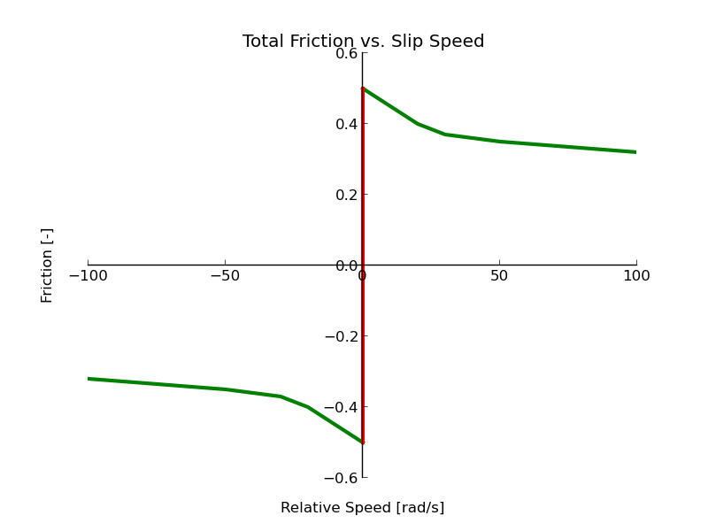
Figure 3 shows a complete picture of the clutches behavior (normalized by the normal force).

Note that we are plotting the friction coefficient as a function of relativel angular velocity. This is normalized to the normal force (i.e. the independent axis shows what fraction of the normal force translates into torque).
The green line shows the friction computed when the clutch is slipping (i.e. the relative speed across the clutch is non-zero). This is the so called "dynamic friction" (i.e. the friction generated when the plates are moving).
The red vertical line represents the behavior of the clutch when it is stuck, Δω=0. This represents the "static friction" (i.e. the friction when the plates are not moving with respect to each other). However, the equation Δω=0 represents an infinite line but the red line isn't infinite. This is because of the torque capacities. As we discussed earlier, the point where the red and green lines meet represents the torque capacity of the clutch. Finally, we see that the clutch model is symmetric with respect to relative speed (i.e. the only difference in the curve between positive and negative values for Δω is the sign of the torque (remember, friction must always oppose the direction of motion).
It may seem tempting to model the clutch as not completely "stuck" but just very, very "gummy". In this case, the equation for the "stuck" model could be modeled using the equation:
τ=cΔω
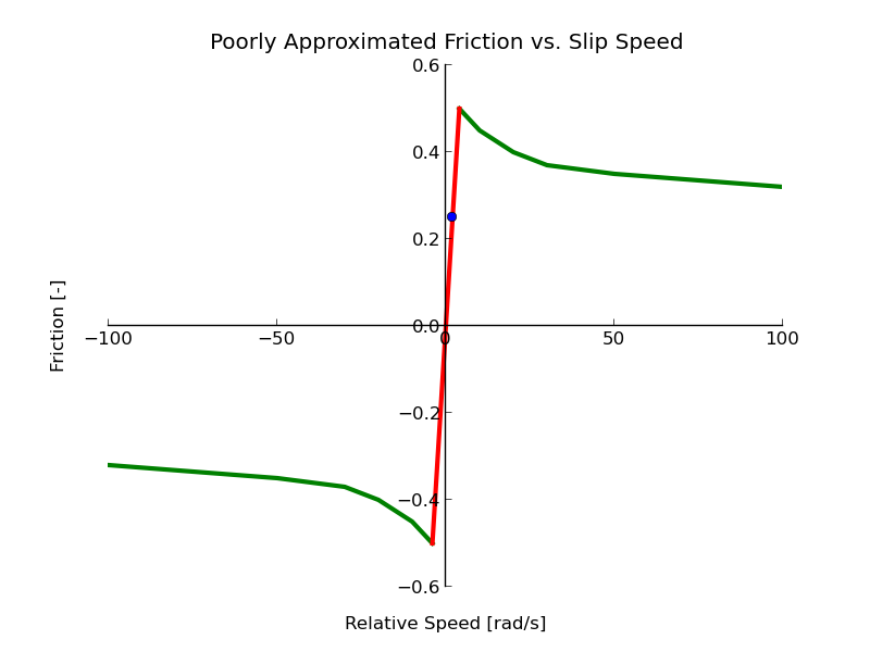
where c is very large. This would, in practice, drive the speed difference to a very small value (because even a small value would generate a large amount of torque). If such an equation were used, the complete behavior could be visualized as shown in Figure 4.

Again, the green line represents slipping (and is identical to Figure 3). However the sticking behavior is more like an extremely viscous damper. While such a clutch is easier for some simulation tools to simulate, it isn't a very good model of a clutch. The reason can be seen when you consider the highlighted point in Figure 4. It shows a point in the "sticking" regime but we can plainly see it isn't really sticking since the relative angular velocity is not zero. This has two disastrous consequences. First, the two elements are not moving at the same speed so if you build a transmission model populated by such clutch models you will get the wrong "gear ratio" from the transmission from the cumulative effect of all these slipping clutches. But equally bad is the fact that such a clutch can dissipate a large amount of power since dissipated power is τΔω and Δω is no longer zero in this case. This means you your system will appear to be much less efficient than it really would be with proper clutches.
An Aside About States
The last thing that makes a friction clutch tricky is the fact that the number of states in the system change dynamically depending on the clutches behavior. When the clutch is slipping, the elements on either end of the clutch are free to move. So each element will have its own angular position and angular velocity states which means the complete system has four states (since all values are independent). But when the clutch exhibits its "stuck" behavior, the speeds of the two elements must be the same and the difference in the angular position remains constant. So when the clutch is stuck, there are only two states (because the speed and angular position of one element are dependent on the speed and angular position of the other).
In mathematical terms, we call this a "variable index system". This is because if we write down the equations for all the parts in this system, we end up with a differential-algebraic equation (DAE). All DAEs have a property known as the "index" which is a way of measuring how "far" the DAE is from being a simple ODE. When switching between the slipping and sticking behavior, we change the index of the DAE. This has profound physical and mathematical implications that are, unfortunately, beyond the scope of this discussion.
Kinematic Clutch
An alternative model for clutch behavior is described in part two of this article.
Share your thoughts
comments powered by Disqus