Posted: January 28, 2013
Implicit Differentiation
Introduction
There is a trick I have come across many times that I had never really seen written up properly. So I thought it might make a nice topic for a blog post.
This trick applies to components which are governed by a kinematic relationship. Typically, these end up being two port devices. As such, you need two equations for relating the through and across variables. The kinematic constraint itself generally gives you one of those equations. But you can typically derive the second equation from a conservation of energy formulation1. But how you do this can make a big difference.
Example #1: An Ideal Gear
Ideal Gear Kinematics
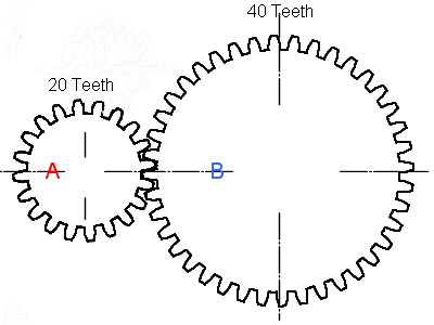
For an ideal gear where we assume the housing is grounded2, you can express the kinematic relationship between the two gear angles using the following relationship:
\[ \phi_a = R \phi_b \]
As I mentioned at the start, this gives us one equation. But we'll need two equations. Generally, this second equation should involve the torques through the component. But can we derive a relationship between those torques?
Conservation of Energy in an Ideal Gear
The normal derivation for such a gear would go something like this:
\begin{aligned} \sum{\frac{dE}{dt}} & = 0 \\ \tau_a \frac{d\phi_a}{dt} + \tau_b \frac{d\phi_b}{dt} & = 0 \\ \tau_a \omega_a + \tau_b \omega_b & = 0 \\ \end{aligned}
The last equation is simply a representation of the fact that the component cannot store power, so the sum of all power into the component must be zero. Note I am using the Modelica sign convention here (positive = into the component). The Modelica code for such a model might look like this:
model IdealGear_TimeDerivative
  "Ideal gear model using a time derivative formulation"
  parameter Real R "Gear ratio";
  extends PartialTwoFlanges;
equation
  flange_a.phi = R*flange_b.phi;
  flange_a.tau*der(flange_a.phi)+flange_b.tau*
    der(flange_b.phi) = 0;
end IdealGear_TimeDerivative;
Digging a Little Deeper
If we use the following equation:
\[ \tau_a \omega_a + \tau_b \omega_b = 0 \]
our system of equations will become "singular" if the speeds go to
zero3 because the references to the torque variables will
disappear. For example, the previous model,
IdealGear_TimeDerivative, will trigger a divide by zero error in some
Modelica tools in such circumstances.
Typically, people take one additional step in the derivation, which is to recognize that \( \omega_a \) and \( \omega_b \) are related (by differentiating the kinematic relationship) as follows:
\[ \omega_a = R \omega_b \]
Substituting this back into the previous equation gives us:
\[ \tau_a R \omega_b + \tau_b \omega_b = 0 \]
Then it is a simple matter to divide through by \( \omega_b \) and in this way we eliminate the dependence on time and eliminate the risk that the equation will become singular at zero speed. However, there is a more general way to approach such problems.
Generalizing
The key here is to avoid any dependency on time. We start again with a conservation of energy formulation, differentiate with respect to time and then expand the various terms that contribute to the power balance:
\[ \sum \frac{dE}{dt} = 0 \]
\[ \tau_a \frac{d\phi_a}{dt} + \tau_b \frac{d\phi_b}{dt} = 0 \]
However, at this point we multiply through by \( dt \), leaving us a relationship between the differential displacements in the system:
\[ \tau_a {\color{red}{d\phi_a}} + \tau_b {\color{red}{d\phi_b}} = 0 \]
Dividing through by one of the differential displacements, we end up with:
\[ \tau_a \color{red}{\frac{d\phi_a}{d\phi_b}} + \tau_b = 0 \Rightarrow \tau_a {\color{red}R} + \tau_b = 0 \]
where \( \frac{d\phi_a}{d\phi_b} \) can be easily derived from our kinematic relationship. The advantage of this approach is that we can derive all the equations we need from the kinematic constraint and those equations will work, regardless of speed. Written in Modelica, this more robust model would look as follows:
model IdealGear
  parameter Real R "Gear ratio";
  extends PartialTwoFlanges;
protected
  Real da_db = R;
equation
  flange_a.phi = R*flange_b.phi;
  flange_a.tau*da_db + flange_b.tau = 0;
end IdealGear;
Example #2: Crank-Slider
Everyone has probably seen the previous gear derivation before and sidestepped the issue with speeds being present in the equation by using the relationship between \( \omega_a \) and \( \omega_b \). But what if your system isn't a gear? Let's quickly run through how this approach would work with two other systems.
The first is a crank-slider mechanism.
Crank-Slider Kinematics
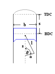
The kinematic relationship in this case would be:
\[ s = a + l - \sqrt{l^2-a^2 sin(\phi)^2} + a cos(\phi) \]
where \( s \) is the height of the piston, \( \phi \) is the angle of
the crank, \( a \) is the crank radius and \( l \) is the rod length.
Again, we need to formulate an equation that relates the
through/flow variables to each other. One approach would be to
derive the following equation:
\begin{aligned} \sum{\frac{dE}{dt}} & = 0 \\ \tau \frac{d\phi}{dt} + F \frac{ds}{dt} & = 0 \\ \tau \omega + F v & = 0 \end{aligned}
This gives us the familiar and unreliable form that includes speeds. If instead, we consider the differential displacements:
\begin{aligned} \tau {\color{red}{d\phi}} + F {\color{red}{ds}} & = 0 \\ \tau + F \frac{\color{red}{ds}}{\color{red}{d\phi}} & = 0 \end{aligned}
where
\[ \frac{ds}{d\phi} = \frac{a^2 sin(\phi)^2 cos(\phi)}{\sqrt{l^2-a^2 sin(\phi)^2}} - a sin(\phi) \]
we end up with a relationship without reference to the speeds. Implementing these relations in Modelica would yield the following model:
model CrankSlider "More robust because it uses differentials"
  parameter Length crank_radius;
  parameter Length rod_length;
  Rotational.Interfaces.Flange_a crank "The crank portion";
  Translational.Interfaces.Flange_a slider "The slider portion";
protected
  Real ds_dphi(unit="m/rad");
equation
  slider.s = crank_radius+rod_length-
     (sqrt(rod_length^2-crank_radius^2*sin(crank.phi)^2))+
             crank_radius*cos(crank.phi);
  ds_dphi = (crank_radius^2*sin(crank.phi)*cos(crank.phi))/
     (sqrt(rod_length^2-crank_radius^2*sin(crank.phi)^2))-
            crank_radius*sin(crank.phi);
  slider.f*ds_dphi + crank.tau = 0;
end CrankSlider;
Example #3: Continuously Variable Transmission (CVT)
Now we consider an even more complex case, that of a continuously variable transmission. What makes a CVT tricky is that you have a complex relationship between the position of the sheaves (also called cones), which are pushed in and out, and the torque transmitted through the belt to the pulleys.
This is visualized in the following diagram:
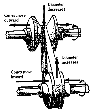
The key question here is how forces on the sheaves affect the position of the belt on the pulley. As in the previous cases, we end up with an equation involving power contributions to an overall power balance, i.e.:
\[ F_1 v_1 + F_2 v_2 = 0 \]
or, more specifically:
\[ F_1 \color{red}{\frac{d{s_1}}{d{s_2}}} + F_2 = 0 \]
But how do we compute \( \frac{d{s_1}}{d{s_2}} \)?
To answer that, we need to first introduce a few geometric relationships for CVTs. The first is the relationship between the displacements between the sheaves, \( s \), and the diameter at which the belt contacts the pulleys, \( D \):
\[ D_1 = \bar{D}_1 + c_1 (s_1 - \bar{s}_1) \]
\[ D_2 = \bar{D}_2 + c_2 (s_2 - \bar{s}_2) \]
where the subscripts indicate which pulley the relationship applies to. In addition, we have the following relationship between the overall belt length, L, and the contact diameters, \( D_1 \) and \( D_2 \):
\[ L = 2 C + \frac{2}{\pi} (D_2 + D_1) + \frac{(D_2 - D_1)^2}{4 C} \]
where \( C \) is the distance between the axis of rotation for the two pulleys.
You are probably wondering how those relationships help us (particularly the last one). To find out, let's start differentiating those relationships and then substituting them into each other.
\[ d{D_1} = c_1 d{s_1} \]
\[ d{D_2} = c_2 d{s_2} \]
\[ dL = \frac{2}{\pi} (d{D_2} + d{D_1}) + 2 \frac{(D_2 - D_1)}{4 C}(d{D_2} - d{D_1}) = \color{red}{0} \]
Let's get rid of the diameters and replace them with the displacements of the sheaves:
\[ (c_2 d{s_2} + c_1 d{s_1}) + B(s_1,s_2) (c_2 d{s_2} - c_1 d{s_1}) = 0 \]
where:
\[ B(s_1,s_2) = \pi\frac{(\bar{D}_2 + c_2 (s_2 - \bar{s}_2) - \bar{D}_1 - c_1 (s_1 - \bar{s}_1))}{4 C} \]
Our belt constraint has now turned into:
\[ (c_2 d{s_2} + c_1 d{s_1}) + B(s_1,s_2) (c_2 d{s_2} - c_1 d{s_1}) = 0 \]
We can compute \(\frac{d{s_1}}{d{s_2}}\) (via implicit differentiation) as:
\[ \color{red}{\frac{d{s_1}}{d{s_2}}} = \frac{c_2 (1+B(s_1,s_2))}{c_1 (B(s_1,s_2)-1)} \]
which we can then substitute back into this relationship:
\[ F_1 \color{red}{\frac{d{s_1}}{d{s_2}}} + F_2 = 0 \]
to get our missing equation that relates the sheaf forces to each other.
Conclusion
There are many different types of components whose behavior is
essentially to enforce a kinematic constraint. Typically, such
component models utilize conservation of energy to provide the
remaining equation that relates the flow variables. If those
equations reference the speeds in the system, they can be re-factored
to remove their dependency on time (i.e., multiply through by
\(dt\)). To complete the equation, you can divide through by one of
the differential displacements and then compute the resulting
derivatives via implicit differentiation of the original kinematic
relationship.
The Kinematics package on GitHub has been updated with the example models used in this blog post.
-
Ultimately, the equation ends up being in terms of power because we differentiate the conservation of energy equation with respect to time. ↩
-
Assuming gears are grounded is a common source of error in my experience (especially when modeling transmissions). In general, I never assume that a gear is grounded. Instead, I always include the housing/mounting connection explicitly in my models, even if it just goes to ground. I've only compromised on this point here to try to keep things as clear and simple as possible. ↩
-
Note that both speeds will go to zero simultaneously due to the kinematic constraint. ↩
Share your thoughts
comments powered by Disqus